Aluminum Foil Composite Shielding Materials for EMC Engineering: A Technical Selection Guide for Cable Manufacturers and EMC Integrators
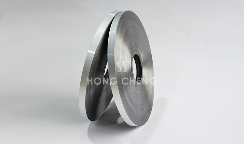
Electromagnetic compatibility (EMC) engineering is fundamentally a shielding problem. Whether the objective is to prevent radiated emissions from a cable harness from disrupting adjacent systems, or to protect a signal cable from external electromagnetic interference (EMI) sources, the shielding layer within the cable construction is the primary engineering control. Aluminum foil composite materials — in various constructions combining aluminum foil with polyester film, non-woven fabric, or conductive fabric — are the dominant shielding medium for data cables, instrumentation cables, and control cables operating in frequency ranges from a few kilohertz to several gigahertz.
For cable manufacturers specifying shielding laminates and for EMC engineers responsible for cable selection and installation, the performance of the shielding layer depends not only on the shielding material itself but on the interaction between material specification, installation practice, and termination method. This guide addresses all three dimensions.
The Physics of Foil Shielding: What the Specification Sheet Tells You and What It Does Not
The standard performance metric for a cable shielding layer is shielding effectiveness (SE), expressed in decibels (dB), measured as the ratio of the incident electromagnetic field to the field transmitted through the shield. A well-designed foil shield on a properly terminated cable can achieve SE values of 60–90 dB across a wide frequency range, which is more than adequate for most industrial and commercial EMC requirements.
The critical word is "properly terminated." Aluminum foil composite shielding materials achieve their rated SE only when the drain wire — the bare or tinned copper wire that runs in contact with the foil throughout the cable length — is correctly connected to a low-impedance ground at both ends (for common-mode noise rejection in differential signal applications) or at a single defined end (for shield drain in single-ended signal applications). The SE of the foil shield itself is largely irrelevant if the drain wire termination introduces impedance discontinuities, creates ground loops, or fails to make consistent electrical contact with the shield.
This distinction matters for material selection because it means that the specification of the shielding laminate must consider not only bulk electrical properties (sheet resistance of the aluminum layer, foil gauge) but also the mechanical and electrical characteristics of the drain wire contact with the foil surface, the long-term stability of this contact under flexing and temperature cycling, and the ease of termination in the cable assembly process.
Foil Composite Constructions: The Main Options and Their Trade-offs
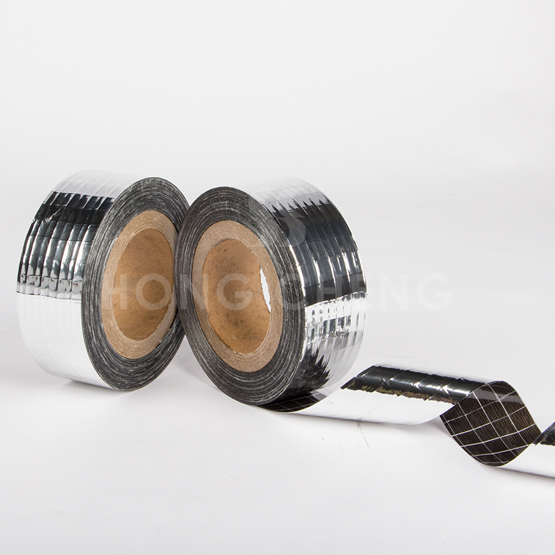
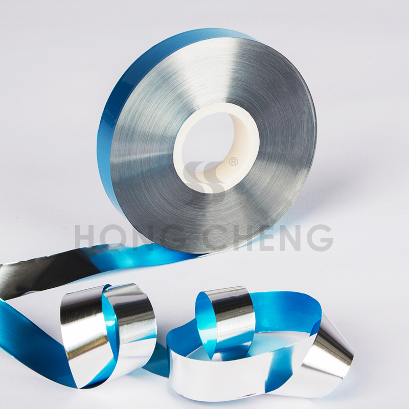
The most widely used shielding laminate in data and instrumentation cables is the foil-polyester (foil-Mylar) composite: a layer of aluminum foil, typically 6–12 microns thick, bonded to a biaxially oriented polyester (PET or Mylar) film, typically 12–25 microns thick. The PET backing provides mechanical support for the thin aluminum layer, preventing foil cracking or fragmentation during cable bending and flexing, and allows the laminate to be processed through cable stranding and extrusion lines without tearing.
Foil-PET composites are available in two configurations relative to the cable construction: with the foil side facing inward (toward the insulated conductors) or with the foil side facing outward (toward the cable jacket). The inward-facing foil configuration provides better electrical contact between the foil and the drain wire and minimizes contact resistance at the shield termination point. The outward-facing foil configuration is used in some constructions where the foil layer also functions as a barrier against jacket compound migration.
For applications requiring higher mechanical robustness — cables intended for repeated flexing in machine tool environments, drag chain installations, or robotic arm harnesses — foil-non-woven composite laminates, combining aluminum foil with a fibrous non-woven substrate, offer improved tear resistance and resistance to foil cracking under cyclic bending. The non-woven substrate provides isotropic mechanical reinforcement compared to the uniaxial tear resistance of PET film, making foil-non-woven laminates preferred in high-flex applications where foil-PET composites would eventually develop microcracking in the aluminum layer.
For extremely high-frequency applications — cables operating above 1 GHz, board-level shielding in dense PCB assemblies, and connectorized shielding enclosures — conductive fabric laminates combining a metallized fabric (typically nylon or polyester with aluminum or copper-nickel coating) with a carrier layer provide the necessary combination of high surface conductivity, flexibility, and drapeability that neither foil-PET nor foil-non-woven can match at the same weight and thickness. These materials are primarily used in device-level EMC enclosures and gasket applications rather than in cable construction.
Foil Gauge and Sheet Resistance: Specification Parameters That Matter
The aluminum foil layer in a cable shielding composite typically ranges from 6 to 20 microns in thickness. The relationship between foil gauge and shielding performance is not linear across all frequencies:
At low frequencies (below approximately 1 MHz), shielding effectiveness is primarily determined by the quality of the ground connection and the absence of apertures in the shield, not by foil thickness. A 6-micron foil and a 20-micron foil will perform identically at these frequencies if both are correctly terminated.
At high frequencies (above approximately 10 MHz), the skin effect means that the relevant parameter is not total foil thickness but the surface conductivity of the foil layer — specifically the sheet resistance of the aluminum surface in contact with the electromagnetic field. At 100 MHz and above, the skin depth in aluminum is approximately 13 microns, meaning that foil layers thicker than 15–20 microns provide no additional SE improvement. For high-frequency shielding performance, the quality of the aluminum surface (surface oxide thickness, freedom from pinhole defects introduced during rolling or lamination) is more important than increasing gauge above 9–12 microns.
Sheet resistance, typically reported in milliohms per square (mΩ/sq), is the most directly meaningful specification parameter for high-frequency shielding. Cable shielding laminates for general-purpose data cable applications should exhibit sheet resistance below 100 mΩ/sq; for performance-critical instrumentation cables and high-frequency data cables, sheet resistance below 30–50 mΩ/sq is preferred.
Drain Wire Compatibility and Contact Resistance
The drain wire in a foil-shielded cable is typically a stranded bare copper or tinned copper wire, ranging from 24 AWG to 18 AWG depending on the current capacity required and the cable construction. The drain wire must maintain consistent electrical contact with the aluminum foil throughout the cable length — in the stranding lay, through repeated bending and flexing, and at the termination point.
A critical and sometimes overlooked compatibility issue is the galvanic potential difference between aluminum and copper. In the presence of moisture, the aluminum-copper contact can drive electrochemical oxidation of the aluminum surface, increasing contact resistance over time. Cable manufacturers can mitigate this effect by specifying foil laminates with a carbon-loaded conductive coating on the foil surface — a thin layer of conductive carbon applied over the aluminum layer that prevents direct aluminum-copper contact while maintaining electrical conductivity. This construction significantly extends the long-term stability of drain wire contact resistance in high-humidity and outdoor cable applications.
For applications where long-term contact resistance stability is critical — instrumentation cables in process plants, control cables in outdoor installations, signal cables in marine and offshore environments — specifying foil composites with this conductive coating is the technically correct choice, even at marginal additional material cost.
Cable Shielding vs. EMC System Design: Where Foil Shielding Fits
Foil shielding in cables is one element of a broader EMC system design. The cable shield attenuates electromagnetic coupling between the cable and its environment, but the overall EMC performance of the system depends on how the cable shield integrates with the grounding and bonding architecture of the equipment it connects.
Common EMC failures attributable to cable shielding are not usually caused by insufficient SE of the foil laminate itself, but by: shield termination resistance at the connector backshell that is too high (often caused by poor crimping, corroded contacts, or inadequate connector selection); ground loops formed when a cable shield is grounded at both ends to chassis grounds at different potential, generating common-mode noise; and shield discontinuities at splices, connectors, or conduit entries that create apertures in the shielding enclosure.
For EMC engineers specifying aluminum foil composite cable shielding, the specification process should therefore include not only the material specification for the shielding laminate (foil gauge, backing material, sheet resistance, drain wire compatibility) but also the termination and bonding specification for the cable assemblies in which the laminate will be used.
Quality Control Parameters for Foil Shielding Laminates
Cable manufacturers qualifying aluminum foil shielding laminates should evaluate the following parameters during incoming material qualification and periodic production quality audits:
Sheet resistance testing (four-probe method, per ASTM B193 or equivalent) to verify foil layer conductivity and detect pinhole defects or oxidation that would increase surface resistance. Peel strength between the foil and backing layer (per ASTM D903 or equivalent) to ensure lamination integrity under the mechanical stresses of cable stranding and bending. Foil cracking index under mandrel bending (custom test per application flex requirement) to verify mechanical durability for the intended cable application. Dimensional consistency — width tolerance, winding tension, core diameter — to ensure processability on cable production equipment. Adhesive bleed-through testing to verify that adhesive used in the lamination does not migrate to the foil contact surface and increase contact resistance with the drain wire.
Market Developments in 2026
Several developments are affecting the aluminum foil composite shielding market in 2026.
The continued expansion of industrial Ethernet and fieldbus-based automation systems — EtherCAT, PROFINET, EtherNet/IP — is driving demand for higher-specification shielded data cables that can maintain signal integrity in electrically noisy industrial environments. These cables require foil shielding laminates with consistent, low sheet resistance and reliable drain wire contact performance.
The transition to higher-voltage drive systems in industrial motors and frequency converters is increasing the severity of common-mode noise in cable trays, placing higher demands on the shielding effectiveness and grounding quality of instrumentation and signal cables routed in proximity to power cables.
Growing demand for halogen-free cable constructions in buildings and rolling stock applications is driving interest in foil shielding laminates compatible with halogen-free jacket compounds, which have different adhesion and processing characteristics compared to PVC-jacketed cable constructions.
Hongcheng Technology manufactures aluminum foil composite shielding laminates for cable and EMC applications, including foil-PET composites, foil-non-woven composites, and conductive-coated foil variants for enhanced drain wire compatibility. Custom widths, foil gauges, and backing film specifications available. Technical data sheets and qualification samples available on request.
Reference standards: ASTM B193, ASTM D903, IEC 62153-4 (EMC cable shielding measurement), EN 50289 (cable measurement methods), MIL-DTL-17 (military cable specifications).
Aluminum Foil Composite Materials in HVAC Ductwork: Fire Ratings, Compliance Standards, and Installation Acceptance Criteria
Aluminum Foil Industrial Flexible Packaging Materials: A Selection Guide for Chemical, Agricultural, and Industrial Applications in 2026